
Dialog Edit dimension
The dialog changes one dimension: mode, text, tolerance, arrows and decimal places. It opens by itself as soon as an element or angular dimension is placed, otherwise by double-clicking a dimension or via the right-click menu ✎ Edit dimension…. It can be moved and can be open at the same time as the attribute panel.

Fields
Preview
Shows the dimension text as it appears in the drawing — with prefix, suffix, tolerance and underline, in the font of the dimensioning. Deviations stand aligned one below the other, signs in their own column.
driven / driving / detached
The three buttons ⟳ driven, 🔒 driving and ✂ detached choose the mode; the active one is highlighted, the change acts immediately and is confirmed in the status bar (Dimension is now DRIVING etc.). driving is disabled for point-to-point dimensions, parallel distances, arc length dimensions, dimensions through a viewport and for fixed elements.
Prefix, Ø, R
Text before the number. The buttons Ø and R set the diameter sign or the R as prefix — for dimensions that have no radius or diameter type of their own, such as a point-to-point dimension across a circle.
Value
The dimension value. Driven: locked, shows the measured value (tooltip Driven (reference) dimension — not editable). Driving: type it in, Enter or OK sets the geometry; invalid values (0, negative, angle ≥ 360°) leave the dimension driven (Invalid value — the dimension stays driven). Detached: free text, empty = dimension line only.
R ⟷ ⌀, Arrow: inside/outside
Only for radius and diameter dimensions. R → ⌀ / ⌀ → R converts the dimension type (Dimension type: Diameter (⌀)); a driving value is re-measured. Arrow: inside / Arrow: outside sets the arrowhead; for a radius outside hides the line from the arc to the centre.
Suffix, underline
Text after the number (for example H7 or a unit). The underline check box underlines the dimension text per DIN — for dimensions not to scale.
Arrows: ↤ Side 1, Side 2 ↦
Only for linear dimensions (linear, point-to-point, rectangle, segment, distance dimensions). Each button hides or shows arrowhead and extension line on its side — side 1 at the first, side 2 at the second reference point. Status bar: Dimension arrow side 1 hidden.
Decimals
Decimal places for this dimension only, 0 to 6; Default = default from the Dimension Settings. The choice reformats the value field at once.
Tolerance

| Choice | Fields | Display |
|---|---|---|
| none | — | the number only |
| symmetric (±) | ± | 40 ±0.1 |
| upper/lower deviation | upper, lower | two lines after the number |
| tolerance class | Class | 40 H7 |
| class + deviations | Class, upper, lower, ⚙ determine | 40 H7 (+0.025 / 0) |
| limit dimensions | Class, upper limit, lower limit, ⚙ determine | 40 (40.02 / 39.98) |
⚙ determine reads the deviations for the entered class and the nominal size from toleranzen.json: capital letters count as hole, lower-case letters as shaft; for limit dimensions nominal size ± deviation is entered. The status bar reports the result (Hole H7 @ 40 mm → upper +0.025 / lower 0 mm). If the class is missing: Please enter a tolerance class first (e.g. H7 for a hole, g6 for a shaft); if the value is invalid: No valid nominal size available to determine; if the table has no entry: class not found. Determined deviations are updated automatically when a driving value changes later; hand-typed ones stay. In the detached mode the tolerance is dropped.
◇ Attributes…, Cancel, OK
◇ Attributes… opens the attribute panel of this dimension, the dialog stays open. OK (also Enter in a field) applies everything and reports Dimension text updated; Cancel (also Esc) discards.
Attribute panel
The floating panel Dimension shows the display values of one dimension (or several selected dimensions) and changes them immediately. Access: Ctrl+double-click on a dimension, right-click ◇ Dimension attributes… (for a chain ◇ Chain dim. attributes…), button ◇ Attributes… in the Edit dimension dialog. When the dimension tool is active, the same panel shows the defaults for the next dimensions under the title Defaults for new dimensions.

| Field | Meaning |
|---|---|
| Header | dimension type and current value, such as Linear = 140 |
| Height (mm) | text height of this dimension |
| Dec. | decimal places |
| Unit | mm, cm, m, m/cm (Bau) |
| Dim. type | apply a dimension style completely to the dimension (Dimension style “…” applied) |
| Zeros: hide | drop trailing zeros |
| Color | colour of this dimension |
| Dimension arrows (mm): Arrow length, Arrow width, Overshoot | as in the settings dialog, but for this dimension only |
| Prefix, Suffix | as in the Edit dimension dialog |
| Offset | offset of the dimension line from the element (element dimensions only) |
| Arrows: Auto / Inside / Outside | Auto flips the arrows outside when the dimension is too tight; Inside and Outside force the position |
The footer reminds you: Value, tolerance, driving/driven: double-click the dimension.
Properties panel
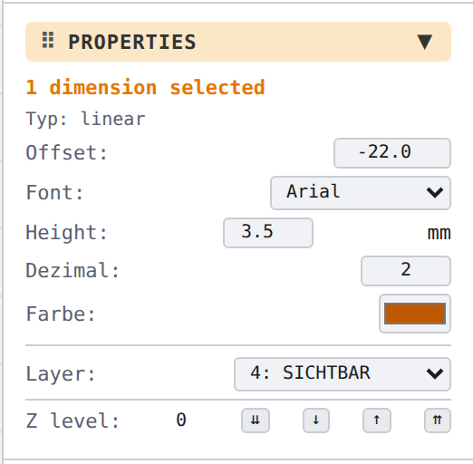
When a dimension is selected (Select tool), the Properties panel on the right shows 1 dimension selected (for chain members 1 chain dimension selected) with the internal type, the offset, for point-to-point dimensions the style (Aligned, Horizontal, Vertikal), font, height, decimals, colour, the layer (list of all drawing layers; — no layer — for a dimension without a layer, — mixed — for several) and the Z level with the four stacking buttons. Every change acts only on the selected dimensions, never on the default.
Right-click menu
Right-click on a dimension shows at the top the entries ✎ Edit dimension… (Double-click) and ◇ Dimension attributes… (Ctrl+double-click); for a chain member the second one reads ◇ Chain dim. attributes…, followed by ◇ Insert chain dimension…. Under Recent commands is the last dimensioning function used. Further down, Dissolve dim. chain breaks a selected chain apart, and Pick up attributes J adopts the values of the dimension as default.

System layer Dimensions
In the layer panel, below the drawing layers, sits the system layer ◇ Dimensions. Its eye hides and shows all dimensions, feature control frames, datum features and balloons together. Hidden dimensions are neither visible nor selectable. The switch is also available as Visible in the dimension section of the Settings dialog.
In addition, every new dimension lies on a drawing layer: if a layer with the name from the field Layer name of the box Dimension layer in the Settings dialog exists (factory Mass), it lands there, otherwise on the active layer. Eye and lock of that layer act on the dimension: hidden it is invisible, locked it can neither be selected nor edited by double-click or right-click. The layer of a selected dimension can be changed in the Properties panel; on DXF export it is written. Dimensions from older drawings without a layer stay unchanged (— no layer —).

Print dialog
Under Line widths (mm) stands the row ◇ Dimensions: (1) with the print width of dimension lines and extension lines in millimetres (factory 0.2; usually 0.25). It applies to linear, rectangle, radius, diameter and angular dimensions. Below it the note: arrow length and text height come from the Dimension Settings and are on paper at scale 1:1 as on screen. With the profile From drawing the fields are disabled.

DXF
On DXF export dimensions are written exploded — one block per dimension with dimension lines, extension lines, arrows and text on the dimension layer (factory name Mass, adjustable in the Settings dialog). The description of the dimension travels along; LiberoDraft reads a real dimension from it again on import. Foreign DXF dimensions (linear, aligned, diameter, radius, three-point angle) are adopted as dimensions when the associated geometry is found. The DXF options are described with the hatch topic.